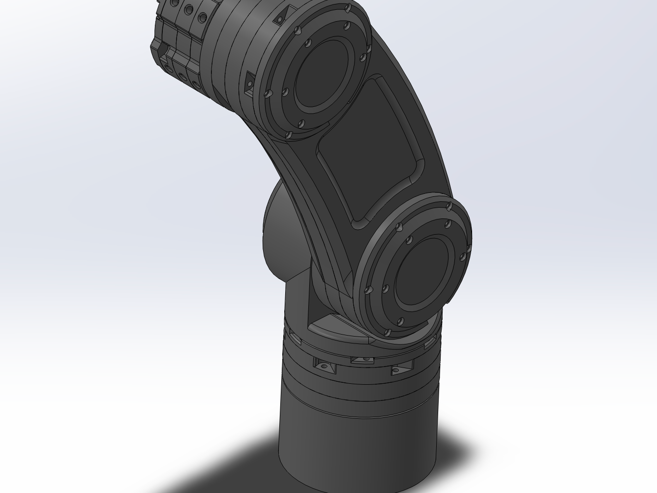
Designed and built two compact cycloidal gearbox variants to provide high torque density and precise motion control for a custom robotic arm. The first actuator achieves a 30:1 reduction and was optimized for high-load joints such as the base, shoulder, and elbow, while a second lightweight 20:1 variant was developed for wrist joints where minimizing mass and inertia was critical. Both systems were manufactured primarily from 3D-printed components and off-the-shelf hardware, with backlash minimized through iterative tolerance tuning and manufacturing compensation. The actuators provide a low-cost alternative to commercial robotic gearboxes and were designed for integration into compact robotic systems.
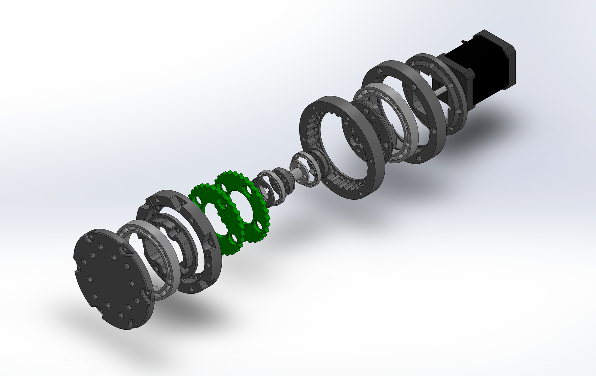
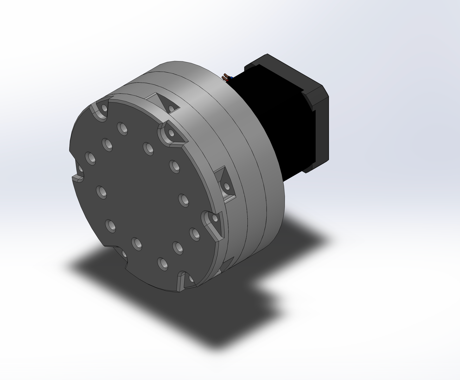
30:1 High-Torque Actuator
Designed for base, shoulder, and elbow joints where torque demand is highest
Larger housing with additional bearing support for improved load capacity
Dedicated output plate and bushing interfaces to reduce wear and improve durability
Prioritizes torque output and structural stiffness over weight
Optimized for supporting downstream links, actuators, and payloads
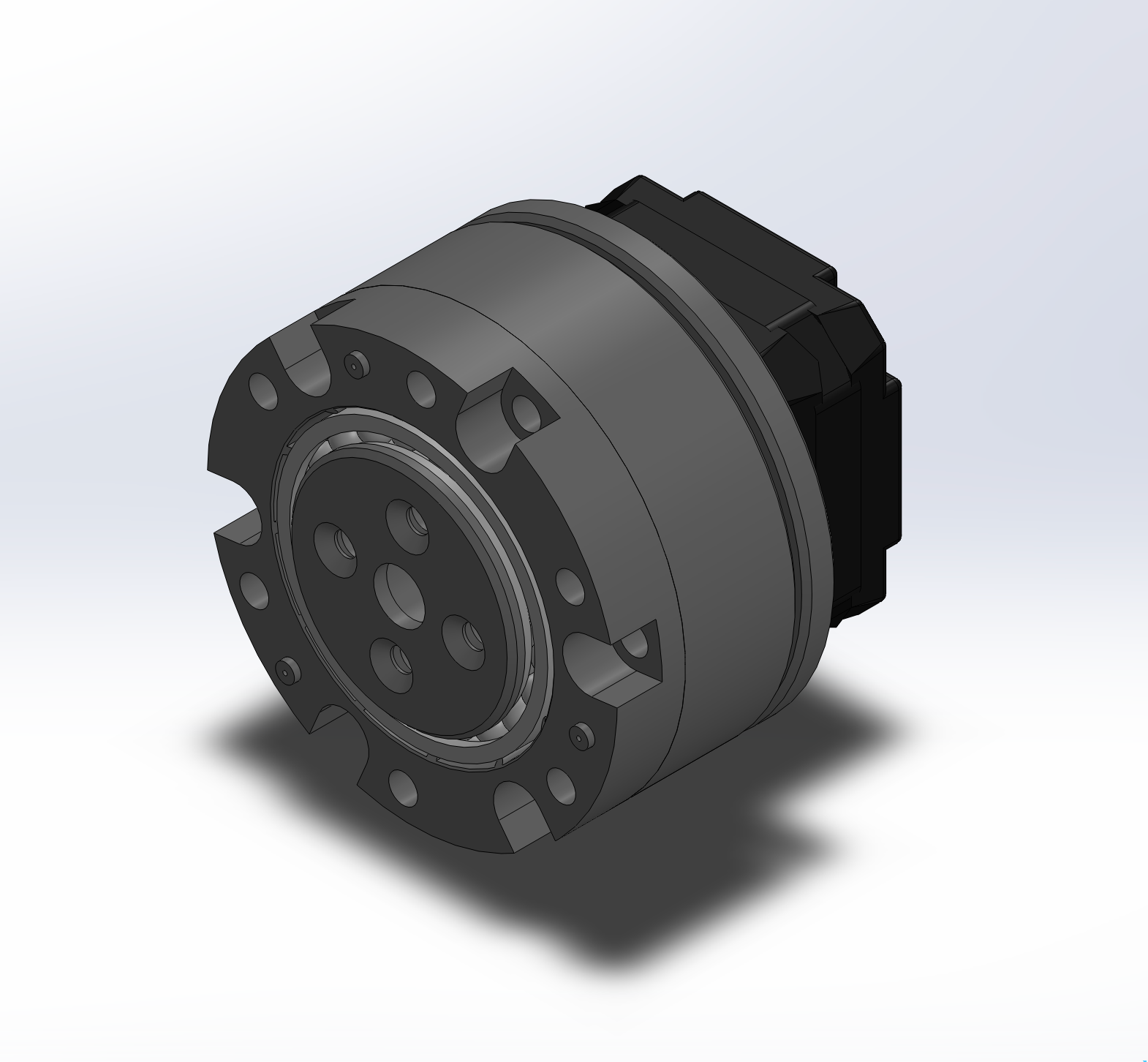
20:1 Lightweight Actuator
Designed for wrist joints where mass and rotational inertia are more critical than maximum torque
Uses a NEMA 17 pancake motor for a more compact package
Simplified housing architecture with reduced part count
Smaller and lighter assembly to improve joint responsiveness
Prioritizes weight reduction and compact packaging while maintaining precise motion control
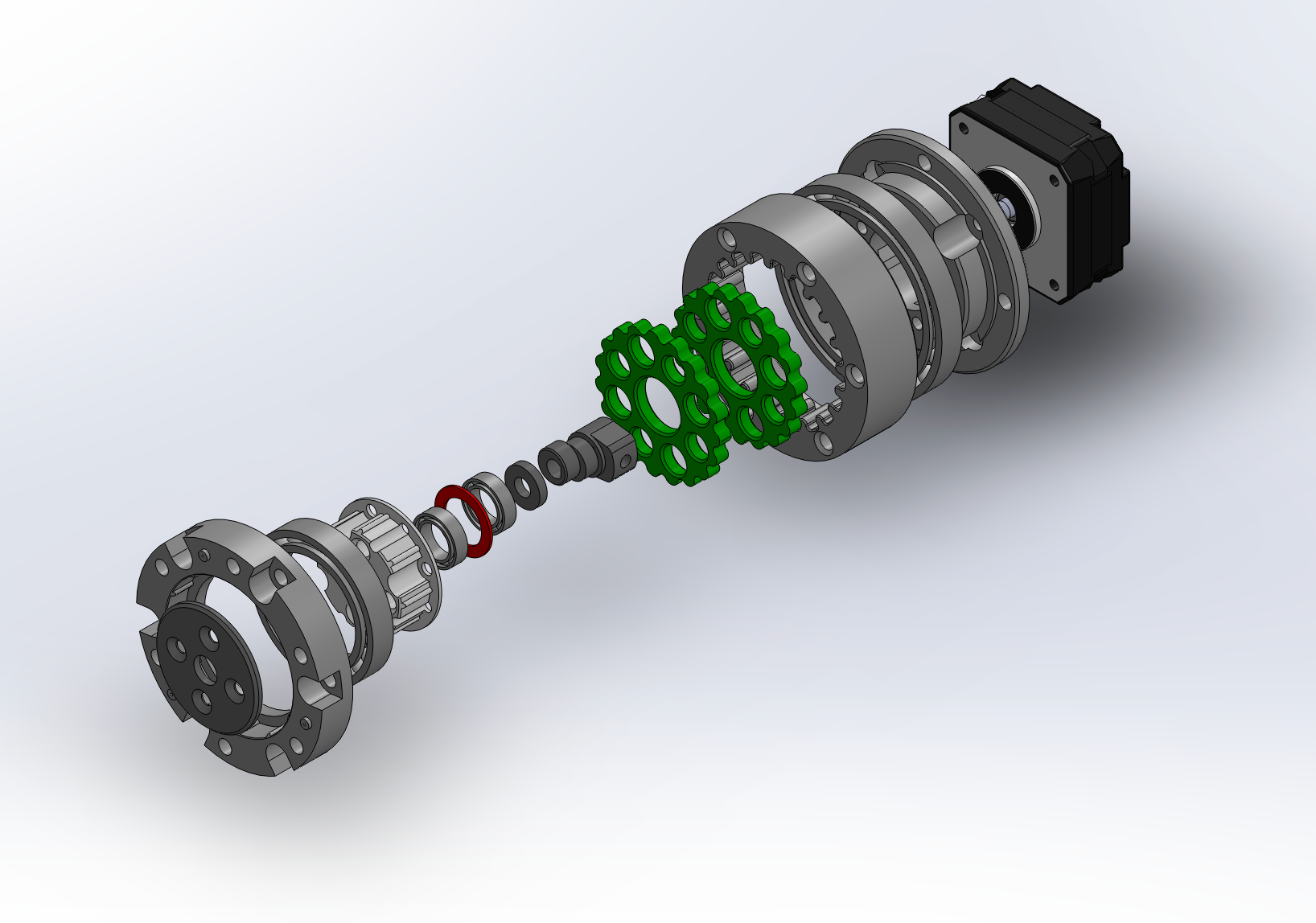
The 30:1 gearbox consists of
14 PETG 3D printed parts
3 different types of bearings
Standoffs used to position and support bearings
Pins and bushing enabling smooth sliding on the disc
Heated inserts for durable fastening
M3 screws for assembly
Nema 17 Motor (0.84 Nm)
DM556 Microstep Driver
Challenges Faced
Some of the main challenges included accurately designing the cycloidal profile and ensuring proper meshing. This was resolved by referencing a paper that outlined how to generate the geometry in SolidWorks using the equation-driven curve tool, allowing for precise and repeatable profile creation. The paper can be found here.
Achieving proper fit was challenging due to 3D printing tolerances, which introduced backlash. Instead of redesigning the system, I identified the issue as dimensional inaccuracy and corrected it by adjusting XY compensation by 0.05 mm, eliminating backlash and improving fit.
Next Steps
I am integrating an AS5600 Magnetic Encoder Module to measure the absolute output angle of the gearbox. Using its I2C interface, I am already able to read precise angular position directly from the output shaft. This enables closed-loop control, eliminating the need to rely on motor step counts, which was unreliable due to the 30:1 reduction requiring ~30 motor rotations for one output rotation.