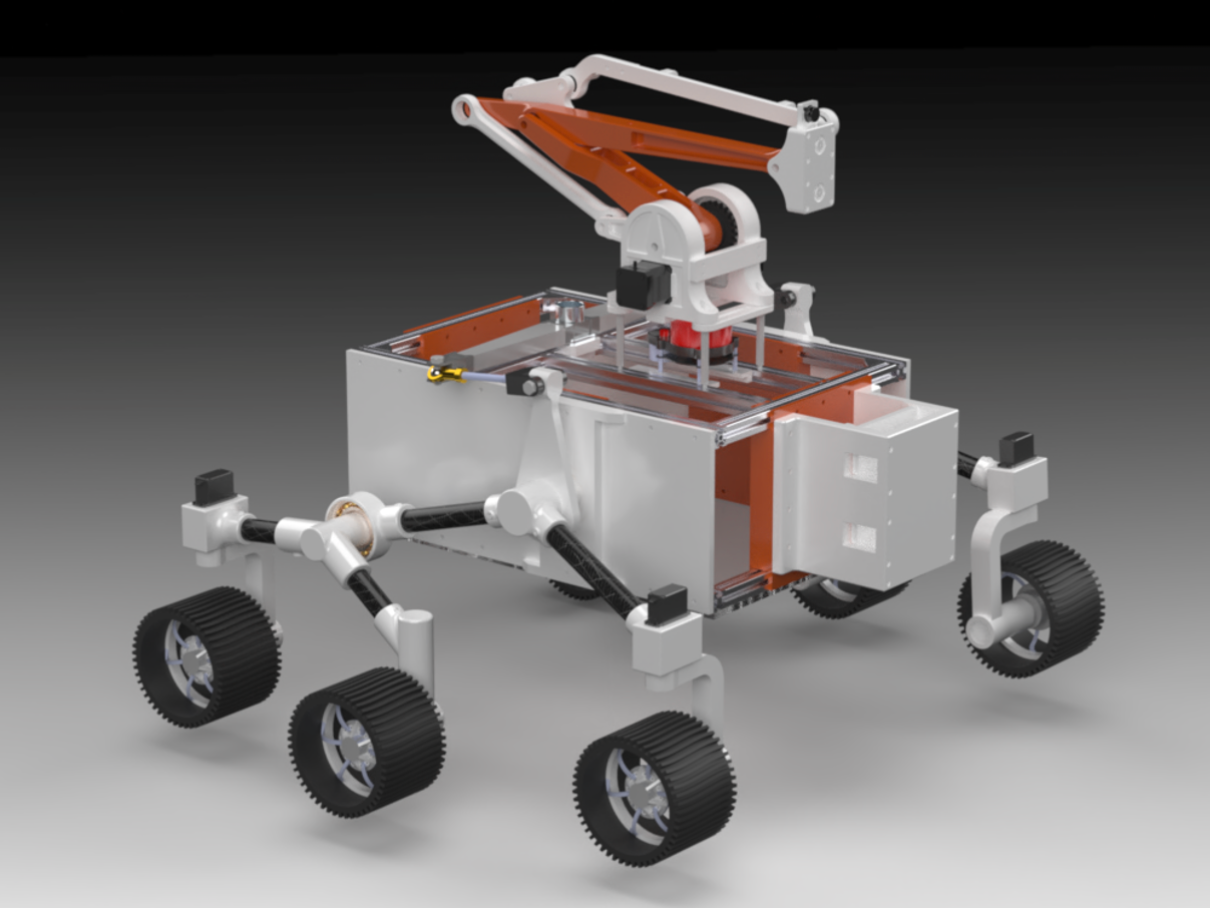
Dyno was a search-and-rescue quadruped robot developed to reach earthquake survivors trapped in rubble too narrow and unstable for human responders, and deliver basic supplies like water and a radio. As the Systems Integration and Testing Engineer responsible for the robotic arm subsystem, I led the design, integration, and validation of a 4-DOF manipulator capable of lifting and accurately positioning a 1 kilogram payload, within a 4 kilogram total system weight limit and a 300 dollar budget.
While the project began as a mechanical design challenge, it quickly evolved into a multidisciplinary systems problem involving actuator selection, controls integration, structural optimization, power management, and validation testing. Working across mechanical, electrical, and software interfaces, I integrated servo-driven actuation, developed control architectures, validated structural performance through simulation and physical testing, and evaluated the relationship between actuator capability, payload capacity, and overall system behavior.
The key objectives include:
Develop a 4 DOF arm within a 4 kilogram total system weight limit, to avoid destabilizing the quadruped platform
Claw must lift at least 1 kg and grasp an object up to 75 mm in diameter, sized to carry rescue items like a water bottle or radio
Validate structural integrity through stress analysis and load testing
Test remote controlled operation for precise object manipulation within ±10 mm
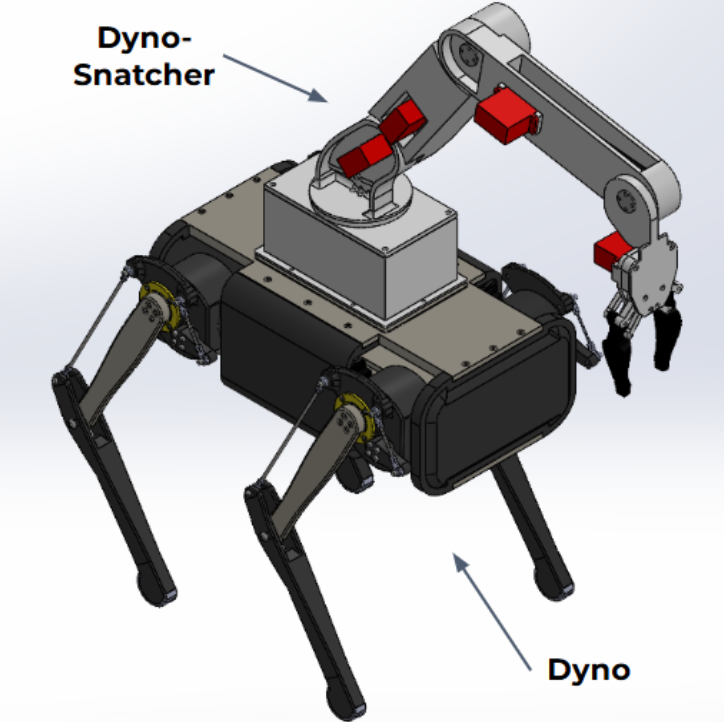
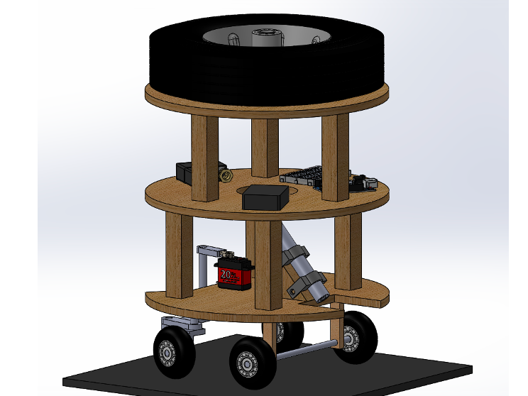
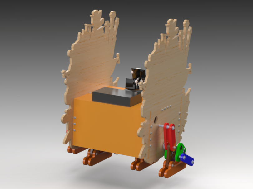
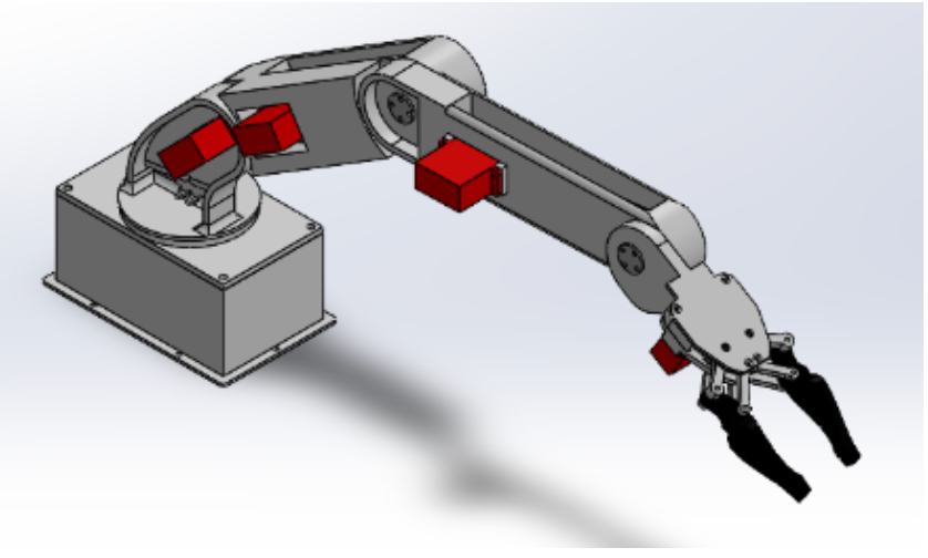
Full CAD Assembly of Dyno and Dyno-Snatcher
Key Contributions
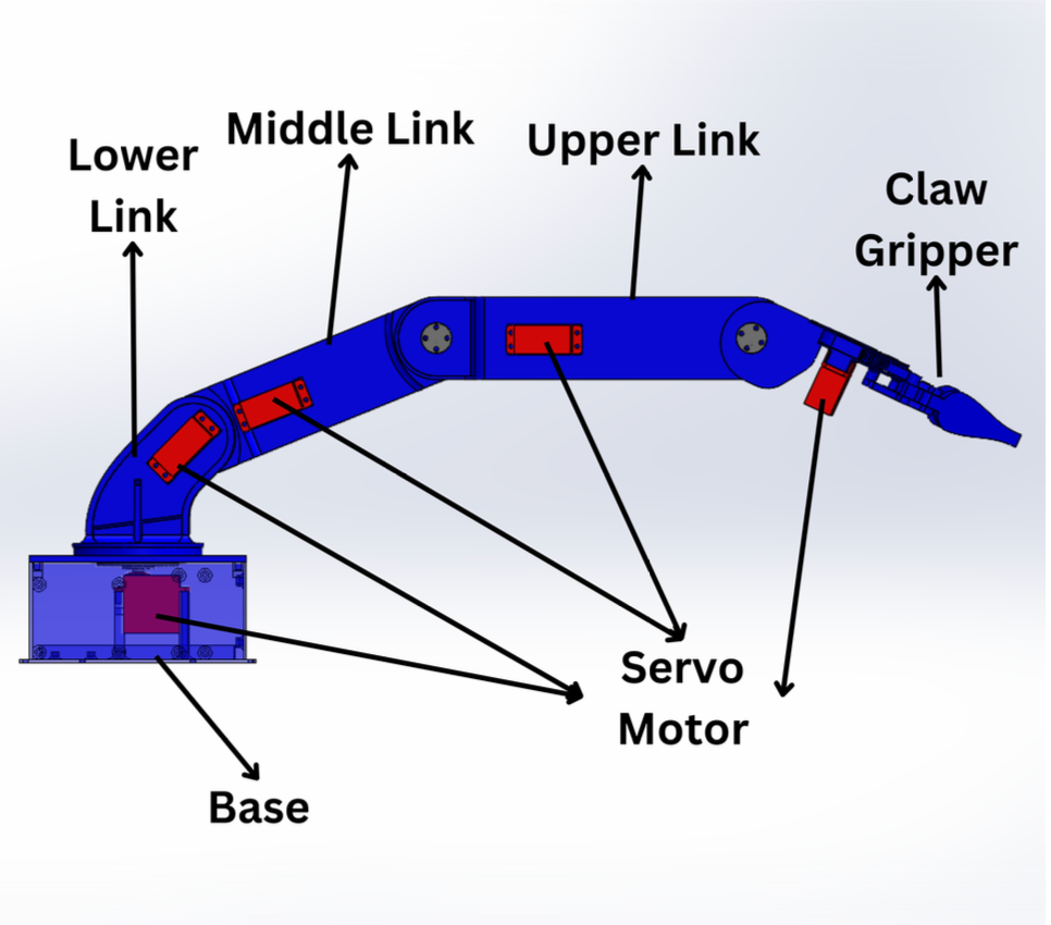
Designed and integrated a 4-DOF robotic manipulator for a quadruped search-and-rescue platform.
Performed system-level trade studies balancing payload capacity, actuator torque, weight, and power consumption.
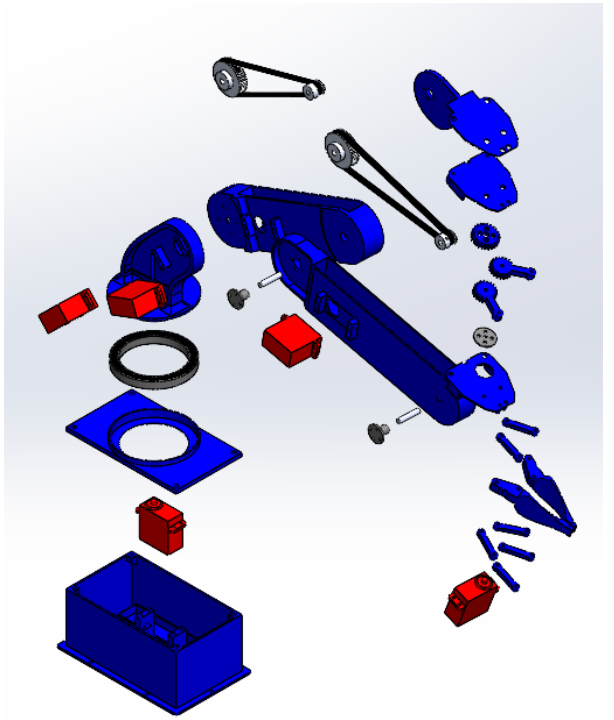
Integrated mechanical, electrical and software subsystems including servos, controllers and power distrubiton.
Conducted structural validation using finite element analysis and physical load testing.
Developed system requirements, subsystem interfaces, verification plans and performance validation procedures.
Lessons Learned
This project fundamentally changed how I approach engineering problems. Initially, I viewed the robotic arm primarily as a structural design challenge. Through testing and integration, I discovered that system performance was driven largely by actuator capability, feedback quality, and the interaction between mechanical, electrical, and software systems.
The project reinforced several key engineering principles:
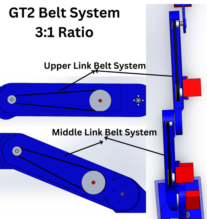
Torque is expensive and must be allocated strategically.
Distal mass compounds loads throughout a robotic arm.
Precision requires feedback, not just commanded motion.
System integration often becomes more challenging than individual component design.
Finite Element Analysis (FEA) Summary
Setup: The part was fully constrained at the servo horn mounting point and subjected to a 3 lbf load in the negative y-direction.
Results:
Maximum Stress: 3.909 MPa, well below PLA’s 60 MPa yield strength.
Maximum Displacement: 0.222 mm.
These results confirm that the design can safely accommodate the applied load with minimal deformation.

FEA SImulation on claw assembly 100% PLA infill
Quarter 1: Research, Design, and Prototyping
Week 2: Initial Research & Concept Development
Research existing designs, identify areas for improvement, and brainstorm components.
Milestone: Preliminary design concepts completed.
Research existing designs, identify areas for improvement, and brainstorm components.
Milestone: Preliminary design concepts completed.
Week 3-4: Requirement Definition & Preliminary Design
Define project requirements (grip force, range, materials) and create early sketches.
Milestone: Requirements finalized, preliminary design drafted.
Define project requirements (grip force, range, materials) and create early sketches.
Milestone: Requirements finalized, preliminary design drafted.
Week 4-5: Technical Research & Component Selection
Research and select motors, sensors, and control boards; refine design for feasibility.
Milestone: Components selected, design refined.
Research and select motors, sensors, and control boards; refine design for feasibility.
Milestone: Components selected, design refined.
Week 5: Design Review & Validation
Review design to align with goals, validate components, and finalize the approach.
Milestone: Design review completed, ready for CAD modeling.
Review design to align with goals, validate components, and finalize the approach.
Milestone: Design review completed, ready for CAD modeling.
Week 6: Detailed CAD Modeling
Create a 3D CAD model, simulate movements, and adjust as needed.
Milestone: CAD model finalized, ready for prototyping.
Create a 3D CAD model, simulate movements, and adjust as needed.
Milestone: CAD model finalized, ready for prototyping.
Week 7: BOM & Assembly Start
Finalize BOM, order parts, and start assembling the structure.
Milestone: Components ordered, initial assembly started.
Finalize BOM, order parts, and start assembling the structure.
Milestone: Components ordered, initial assembly started.
Week 8: Mechanical Completion & Motor Integration
Finish assembly, mount motors, and wire control circuits.
Milestone: Mechanical structure and motors integrated.
Finish assembly, mount motors, and wire control circuits.
Milestone: Mechanical structure and motors integrated.
Quarter 2: Integration, Testing, and Optimization
Week 1-2: Software Development & Initial Testing
Write control algorithms, implement sensor feedback, and test basic functions.
Milestone: Basic software functional.
Write control algorithms, implement sensor feedback, and test basic functions.
Milestone: Basic software functional.
Week 3-4: Calibration & Performance Testing
Fine-tune controls and test grip with various objects.
Milestone: System calibrated and optimized.
Fine-tune controls and test grip with various objects.
Milestone: System calibrated and optimized.
Week 5-6: Integration with Humanoid Robot
Mount the claw, integrate with the main controller, and test interaction.
Milestone: Claw operational with humanoid robot.
Mount the claw, integrate with the main controller, and test interaction.
Milestone: Claw operational with humanoid robot.
Week 7-8: Advanced Development & System Testing
Implement advanced control patterns and test in dynamic environments.
Milestone: Advanced software integrated and tested.
Implement advanced control patterns and test in dynamic environments.
Milestone: Advanced software integrated and tested.
Week 9-10: Optimization & Documentation
Optimize all systems, conduct final tests, and prepare reports and videos.
Milestone: Project complete, ready for presentation.
Optimize all systems, conduct final tests, and prepare reports and videos.
Milestone: Project complete, ready for presentation.